What is a Resistor?
Share
0.0 Introduction
Resistors: the unsung heroes of electronics. These unassuming components are the key to controlling current, voltage, and precision in electronic circuits. In this guide, we'll unravel the world of resistors, from their types and selection criteria to their practical applications and tips for effective use. Whether you're a seasoned engineer or a newcomer to electronics, join us on this journey to demystify these miniature marvels and discover their vital role in the world of technology.
1.0 Definition and Purpose
1.1 What is a Resistor?
In the world of electrical engineering, a resistor is a fundamental electronic component designed to do one thing: resist the flow of electric current. Its purpose may seem straightforward, but the role of resistors in electronic circuits is both critical and versatile.
1.2 Definition
At its core, a resistor is a passive two-terminal component that offers electrical resistance to the flow of current passing through it. This resistance is measured in ohms (Ω), a unit named in honour of the German physicist Georg Simon Ohm, who formulated Ohm's Law, a fundamental principle in electrical engineering.
1.3 Purpose
The primary purpose of a resistor is to control the amount of current flowing in a circuit. By introducing resistance, it restricts the flow of electrons, regulating the voltage and current levels within a circuit. This regulation serves several essential functions in electronic applications:
1.3.1 Voltage Division
Resistors are commonly used in voltage divider circuits, where they create a fraction of the input voltage as an output. This is invaluable in controlling voltage levels for various components in a circuit.
1.3.2 Current Limiting
They act as current limiters, preventing excessive current from flowing through sensitive components, thus protecting them from damage.
1.3.3 Signal Conditioning
In signal processing circuits, resistors play a pivotal role in shaping and conditioning signals to meet specific requirements.
1.3.4 Biasing
Resistors are essential in biasing transistors and operational amplifiers, setting their operating points and enabling them to function as amplifiers.
1.3.5 Temperature Sensing
Some resistors, like thermistors, change their resistance with temperature. These are used for temperature sensing and control applications.
1.3.6 LED Current Limiting
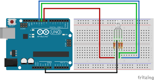
In LED circuits, resistors control the current passing through the LED, preventing it from drawing too much current and burning out.
Resistors come in various shapes, sizes, and materials to suit different applications. Understanding their properties and how to select the right one for a specific task is crucial for any electrical engineer.
In the following sections, we will delve deeper into the types of resistors, their symbols, color coding, values, tolerances, and practical applications to provide a comprehensive understanding of these essential components in electronics.
2.0 Types of Resistors
Resistors are available in various types, each designed to meet specific requirements in electronic circuits. Understanding the different types of resistors and their characteristics is crucial for selecting the right component for your projects. Here, we'll explore some of the most common types of resistors:
2.1 Fixed Resistors
2.1.1 Carbon Film Resistors
Carbon film resistors are among the most commonly used resistors in electronics. They are constructed by depositing a thin film of carbon onto a ceramic substrate. These resistors come in a wide range of resistance values and power ratings, making them versatile components for various applications. They are cost-effective and offer reasonable stability, making them suitable for general-purpose use. Carbon film resistors find their place in a plethora of electronic circuits, from power supplies to signal conditioning.
2.1.2 Metal Film Resistors
Metal film resistors are favoured for applications demanding higher precision. They are crafted by depositing a thin layer of metal, often nickel-chromium or similar alloys, onto a ceramic substrate. This manufacturing process results in resistors with lower noise and improved temperature stability compared to carbon film resistors. Due to their high precision and reliability, metal film resistors are often used in audio equipment, measurement devices, and precision instrumentation.
2.1.3 Wirewound Resistors
When it comes to high power-handling capabilities and accuracy, wirewound resistors shine. These resistors consist of a resistive wire wound around a ceramic or fiberglass core. The wire's length and diameter determine the resistance value and power rating. Wirewound resistors are known for their ability to dissipate heat efficiently, which makes them suitable for high-power applications like power amplifiers, motor control circuits, and industrial equipment where precision and robustness are essential.
These three types of resistors cater to various needs in electronic circuits, allowing engineers to select the most appropriate one based on factors like precision, power handling, and cost-effectiveness.
2.2 Variable Resistors
2.2.1 Potentiometers (Pots)
Potentiometers, often referred to as "pots," are variable resistors that offer manual adjustment of resistance. They consist of a resistive track and a wiper that can be moved along the track. By turning the knob or slider, users can vary the resistance between the wiper and the two ends of the track. Potentiometers are commonly found in applications where manual control is required, such as volume controls in audio equipment, tuning circuits in radios, and adjusting parameters in electronic devices. Their versatility and ease of use make them essential components in many consumer and industrial electronics.
2.2.2 Rheostats
Rheostats are specialized variable resistors designed for current control rather than voltage adjustment. Unlike potentiometers, which have three terminals, rheostats typically have only two terminals. By varying the resistance between these two terminals, rheostats limit the current passing through a circuit. They are often used as current limiters in applications like lighting dimmers, heating elements, and motor speed control. Rheostats provide a simple yet effective means of adjusting and controlling current levels in various electrical systems.
2.3 Surface Mount Resistors (SMDs)
Surface mount resistors, abbreviated as SMDs, are designed for surface mount technology (SMT) applications, which are prevalent in modern electronics manufacturing. These resistors are compact, lightweight, and compatible with automated assembly processes, making them ideal for densely populated circuit boards. SMDs come in various sizes and shapes, such as 0805, 0603, and 0402, denoting their dimensions in imperial units. Their small size and efficient heat dissipation properties make them suitable for applications where space and thermal management are critical, such as smartphones, tablets, and other portable devices. SMDs have become the standard choice for modern electronic components, enabling the miniaturization of electronic products.
2.4 Specialized Resistors
2.4.1 Thermistors
Thermistors are unique resistors that exhibit a significant change in resistance with temperature variations. They are temperature-sensitive components used in various applications, particularly those involving temperature measurement, control, and compensation. Thermistors can be divided into two main categories: NTC (Negative Temperature Coefficient) and PTC (Positive Temperature Coefficient) thermistors. NTC thermistors have resistance that decreases as the temperature rises, making them suitable for temperature measurement and control. PTC thermistors, on the other hand, exhibit resistance that increases with temperature, making them useful in applications like overcurrent protection and self-regulating heaters. The precise resistance-temperature characteristics of thermistors make them invaluable in scenarios where accurate temperature sensing and compensation are paramount, such as in thermostats, automotive engine management systems, and medical devices.
2.4.2 Varistors (Voltage Dependent Resistors, VDRs)
Varistors, also known as Voltage Dependent Resistors (VDRs), are nonlinear resistors that alter their resistance with changes in applied voltage. They are primarily employed as protective devices in electrical circuits, guarding against voltage spikes and surges. Varistors are designed to have high resistance under normal operating conditions but rapidly transition to a low-resistance state when exposed to overvoltage conditions. This characteristic makes them effective in diverting excessive voltage away from sensitive components and preventing damage due to voltage transients. Varistors are commonly used in surge protection devices, power supplies, and electronic equipment to safeguard against lightning strikes, switching transients, and other voltage irregularities, ensuring the longevity and reliability of electrical systems.
Understanding the characteristics and applications of these different resistor types is essential for designing and troubleshooting electronic circuits effectively. In the next section, we will delve into how resistors are represented in circuit diagrams and the colour coding system used to identify their values.
3.0 Resistor Symbols and Colour Coding
Resistors are not only physical components but are also represented in circuit diagrams using standardized symbols. Additionally, they are often colour-coded to indicate their resistance values. In this section, we will explore resistor symbols and the colour code system used for identifying resistor values.
3.1 Resistor Symbols
· Resistor Symbols in Schematics: Resistors in circuit diagrams are typically represented by a zigzag line. The symbol also includes a reference designator, such as "R1," to identify the resistor in the circuit.
· Variable Resistor Symbols: Variable resistors like potentiometers are represented with an arrow or an arrow inside a rectangle to indicate the adjustable nature of their resistance.
3.2 Resistor Colour Coding
3.2.1 Colour Bands:
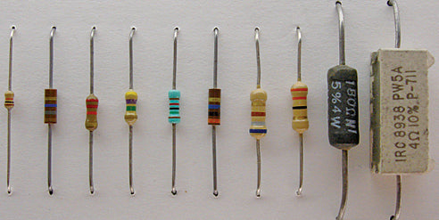
Most through-hole resistors have colour bands painted on them to indicate their resistance values and tolerances.
3.2.2 Colour Code Chart
The colour bands follow a standardized colour code chart. Each colour corresponds to a number, and the combination of colours on the resistor indicates its resistance value and tolerance.
Example: A resistor with bands of brown, black, and red, followed by a gold band, would have a resistance value of 1000 ohms (1 kilo-ohm) with a tolerance of ±5%.
3.2.3 Significance of Colour Bands
· The first band represents the first digit of the resistance value.
· The second band represents the second digit.
· The third band indicates the multiplier (number of zeros to add to the two digits).
· The fourth band (if present) signifies the tolerance.
3.2.4 Tolerance Bands
Tolerance bands come in different colours, with common values being gold (±5%) and silver (±10%). A resistor's tolerance indicates the maximum deviation from its specified resistance value.
Understanding resistor symbols and colour coding is essential for both reading circuit diagrams and selecting the right resistors for specific applications. In the next section, we will delve into resistor values and tolerances in more detail.
4.0 Resistor Values and Tolerances
In this section, we will delve deeper into resistor values and tolerances, providing a comprehensive understanding of how resistors are specified and what these specifications mean for your electronic circuits.
4.1 Resistor Values
4.1.1 Resistance Values (Ohms)
The resistance value of a resistor, measured in ohms (Ω), is a fundamental property that defines how much it resists the flow of electrical current. Lower resistance values allow more current to pass, while higher resistance values restrict it. This property is crucial for controlling the flow of current in electronic circuits, ensuring that components receive the right amount of electricity. For example, in an LED circuit, a resistor with an appropriate resistance value limits the current through the LED, preventing it from burning out while providing optimal brightness.
4.1.2 Standard Values
Resistors are available in standard resistance values organized into E-series, such as E12, E24, and E96. These series offer a wide selection of values with logarithmic spacing between them. The logarithmic progression ensures that there are both high-precision values and values suitable for general applications. Engineers often choose values from these series to simplify design and component sourcing.
4.1.3 Preferred Values
Within the E-series, you'll find preferred values that are commonly used in circuit design. These values, like 10, 22, 47, etc., have practical significance in various applications. Using preferred values makes it easier to find and replace components, which is especially important for maintenance and repair.
4.2 Resistor Tolerances
4.2.1 Tolerance Definition
Tolerance represents the allowable deviation from the nominal (specified) resistance value. It is expressed as a percentage of the nominal value. For instance, a resistor with a ±5% tolerance may have a resistance value that is 5% higher or lower than its specified nominal value.
4.2.2 Common Tolerances
Resistors come with different tolerance levels, including ±1%, ±2%, ±5%, and ±10%. The choice of tolerance depends on the specific application. In precision instrumentation or signal processing circuits, where accuracy is paramount, resistors with tighter tolerances (e.g., ±1%) are preferred. In contrast, for general-purpose applications, a ±5% tolerance is often sufficient.
4.2.3 Impact on Circuit Design
Selecting the right tolerance is critical in circuit design. For circuits where the exact resistance value is not crucial, a resistor with a wider tolerance (e.g., ±10%) can be used to save costs. However, in applications where precision is essential, such as in medical devices or aerospace equipment, resistors with tight tolerances must be employed to ensure reliable and accurate performance.
4.2.4 Colour Band for Tolerance
The tolerance band on a resistor's colour code is used to indicate its tolerance level. This visual coding system simplifies the identification of a resistor's tolerance at a glance. For instance, a gold band signifies a ±5% tolerance, while a silver band indicates a ±10% tolerance.
4.3 Example Resistor Values
4.3.1 Real-World Examples
Real-world examples of resistors with colour codes can help illustrate how to interpret and decode their values. For instance, a resistor with colour bands of yellow, violet, red, and gold signifies a resistance value of 4.7 kilo-ohms with a tolerance of ±5%. Understanding these examples empowers engineers to select and use resistors effectively in their projects, ensuring the desired performance of their electronic circuits.
4.3.2 Useful Tools
In the age of the internet, engineers have access to various online tools and calculators that can quickly decode resistor colour codes and determine their values. These tools simplify the process of working with resistors, especially when dealing with complex colour codes or a wide range of resistance values.
Understanding resistor values and tolerances is crucial for selecting the right resistor for your electronic projects and ensuring the desired performance of your circuits. In the next section, we will explore common applications of resistors in electrical engineering.
5.0 Resistor Applications
Resistors find applications in a wide range of electronic circuits and devices. In this section, we will explore common applications of resistors in electrical engineering, showcasing their versatility and significance.
5.1 Voltage Dividers
Resistors are frequently used in voltage divider circuits. A voltage divider consists of two resistors in series, and it divides the input voltage into a fraction at the junction between them. This technique is crucial for obtaining specific voltage levels required for various components in a circuit, such as sensors or operational amplifiers.
5.2 Current Limiting
One of the primary roles of resistors is current limiting. By introducing resistance in a circuit, they restrict the flow of current to protect sensitive components from excessive current levels. For example, resistors are used to limit the current in LEDs, preventing them from drawing too much current and burning out.
5.3 Signal Conditioning
Resistors play a pivotal role in signal conditioning. In amplifiers and filter circuits, they are used to shape and modify signals to meet specific requirements. Resistor networks are often used in operational amplifier circuits for feedback and gain control, allowing engineers to fine-tune signal amplification.
5.4 Biasing in Transistors
In transistor circuits, resistors are employed for biasing. Biasing establishes the operating point of transistors, ensuring that they function within the desired range. Resistors in biasing networks help stabilize transistor behaviour and prevent distortion in amplifier circuits.
5.5 Temperature Sensing and Compensation
Thermistors, a specialized type of resistor, exhibit significant changes in resistance with temperature. They are utilized in temperature sensing and compensation applications. For instance, thermistors are commonly used in thermostats and temperature control systems.
5.6 Protection Against Voltage Spikes
Varistors, also known as Voltage Dependent Resistors (VDRs), are non-linear resistors that change their resistance with applied voltage. They are crucial for surge protection in electrical circuits, safeguarding sensitive components from voltage spikes caused by lightning, switching, or other transient events.
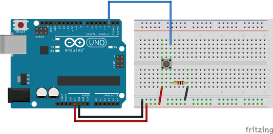
5.7 Pull-Up and Pull-Down Resistors
In digital electronics, pull-up and pull-down resistors are used to ensure that digital inputs to microcontrollers or other digital devices have defined logic levels. These resistors ensure that the input is in a known state when no external input is present.
Understanding the various applications of resistors is essential for designing effective electronic circuits. In the next section, we will explore the factors to consider when selecting resistors for specific applications.
6.0 Factors to Consider When Selecting Resistors
Selecting the right resistor for a specific electronic application is crucial for achieving the desired performance and functionality of your circuit. In this section, we will explore important factors that engineers and hobbyists should consider when choosing resistors.
6.1 Resistance Value (Ohms)
When selecting a resistor, the primary consideration is its resistance value, measured in ohms (Ω). The resistance value determines how effectively the resistor limits the flow of current in a circuit. It is essential to choose a resistor with a resistance value that aligns with the desired current and voltage levels in your circuit. Whether you need to limit current, create voltage dividers, or match impedances, the resistance value is the foundational parameter that ensures your circuit functions as intended.
6.2 Power Rating (Watts)
The power rating of a resistor is a critical factor to prevent overheating and maintain reliable performance. It indicates the amount of heat a resistor can dissipate without changing its electrical properties or failing. Choosing a resistor with the correct power rating ensures it can handle the expected power dissipation in your circuit. Always check the datasheet to confirm that the chosen resistor can handle the power levels without exceeding its rated limit, as overheating can lead to resistor failure and circuit malfunctions.
6.3 Tolerance
Tolerance defines the allowable deviation from the specified resistance value. It is expressed as a percentage. Tolerance is a vital consideration, especially in precision applications where maintaining accuracy is essential. For instance, a resistor with a ±1% tolerance means that its actual resistance value can deviate by no more than 1% from the specified value. The choice of tolerance depends on your circuit's requirements. For general applications, a ±5% tolerance resistor may be sufficient, but in applications where precision is critical, such as in scientific instruments or calibration circuits, tighter tolerance resistors are necessary.
6.4 Temperature Coefficient (TCR)
The temperature coefficient of a resistor (TCR) indicates how its resistance changes with temperature variations. A low TCR resistor exhibits minimal resistance variation with temperature, making it suitable for applications requiring stable performance over a wide temperature range. In contrast, high TCR resistors experience significant resistance shifts with temperature changes. Selecting resistors with an appropriate TCR is crucial in applications where temperature stability is paramount, such as in temperature sensors, precision voltage dividers, and industrial control systems.
6.5 Voltage Rating
To ensure the safety and longevity of your circuit, consider the voltage rating of the resistor. The voltage rating specifies the maximum voltage the resistor can withstand without breaking down or arcing. Using resistors with insufficient voltage ratings can lead to electrical breakdown and failure. Always select resistors that have a voltage rating higher than the maximum voltage they will experience in your circuit to prevent voltage-related issues.
6.6 Noise Performance
In applications where low electrical noise is critical, such as in sensitive analog circuits or audio equipment, it's important to choose resistors with low noise characteristics. Low-noise or precision resistors are specifically designed to minimize unwanted electrical noise and interference, ensuring that your circuit maintains its signal integrity and accuracy.
6.7 Package Size and Type
The physical size and type of resistor package impact your circuit's design, assembly, and board layout. Consider the available space on your PCB and the ease of assembly when choosing the package size and type. Smaller surface-mount packages (SMDs) are ideal for compact designs, while larger through-hole packages may be more appropriate for ease of soldering and heat dissipation in high-power applications.
6.8 Environment and Conditions
Take into account the operating environment where the resistor will be deployed. Factors such as temperature, humidity, exposure to chemicals, and other environmental conditions can affect the performance and longevity of resistors. Choose resistors that are suitable for the specific environmental challenges your circuit will face to ensure reliable and consistent operation.
6.9 Cost and Availability
Evaluate the cost-effectiveness of the chosen resistor while considering its availability for your project's production and maintenance needs. In some cases, specialized resistors may be more expensive but essential for unique applications, while for general purposes, readily available and cost-effective options may suffice.
6.10 Special Requirements
Certain applications may require specialized resistors tailored to unique demands. High-voltage resistors, high-frequency resistors, or high-precision resistors are examples of specialized components designed for specific requirements. Ensure that your selection aligns with any special considerations your project entails, and consult datasheets and manufacturers for guidance on specialized resistor options.
By carefully considering these factors when selecting resistors, you can optimize your circuit's performance, longevity, and reliability. The right resistor choice is essential to ensure your electronic design functions as intended.
In the next section, we will explore resistor networks and arrays, which offer unique advantages in certain circuit designs.
7.0 Resistor Networks and Arrays
While individual resistors serve many purposes, there are situations where using resistor networks or arrays provides unique advantages in electronic circuit design. In this section, we will explore the concept of resistor networks and arrays and their applications.
7.1 What Are Resistor Networks and Arrays?
Resistor networks and arrays are ingeniously designed configurations of multiple resistors housed within a single package. These composite components serve the dual purpose of saving valuable space on printed circuit boards (PCBs) while enhancing the performance and functionality of electronic circuits. By integrating multiple resistors into a single compact package, they simplify circuit design, reduce interconnection complexity, and often improve thermal performance. This ingenious packaging allows engineers and designers to optimize board space, especially in applications with limited real estate.
7.2 Advantages of Resistor Networks and Arrays
7.2.1 Space Efficiency
By integrating multiple resistors into a single component, these devices save valuable PCB space, which is particularly crucial in compact electronic devices.
7.2.2 Accuracy and Matching
Resistor networks often offer better resistor-to-resistor matching than individual resistors. This precision is essential in applications like precision voltage dividers or amplifier feedback networks.
7.2.3 Improved Thermal Performance
Compact resistor networks can provide better thermal performance due to their close proximity. This can be advantageous in high-power applications.
7.2.4 Simplified PCB Layout
Using networks and arrays reduces the number of components on a PCB, simplifying layout design, reducing interconnection complexity, and potentially lowering manufacturing costs.
7.3 Common Types of Resistor Networks and Arrays
7.3.1 Bussed Resistor Networks
These consist of multiple resistors connected to a common bus or pin. They are often used in applications where the same reference voltage is needed across all resistors.
7.3.2 Isolated Resistor Networks
In isolated networks, each resistor is electrically independent, and there is no common connection. This design is suitable for applications where precise isolation between resistors is required.
7.3.3 Voltage Divider Networks
These networks are configured to create precise voltage divisions. They are commonly found in applications like digital-to-analogue converters (DACs) and voltage reference circuits.
7.3.4 Array Packages
Array packages contain multiple resistors in a specific pattern, such as 4x0804, indicating four resistors in an 0804 package size. These are versatile and can be configured for various applications.
7.4 Applications
Resistor networks and arrays find a wide array of applications in electronic devices and systems. They are particularly useful in precision voltage dividers, where balanced resistance values are essential for accurate voltage scaling. In operational amplifier feedback networks, they aid in fine-tuning signal gain and shaping. These composite components are indispensable in digital-to-analogue converters (DACs) for creating precise voltage outputs. Voltage reference circuits benefit from their ability to provide stable and accurate reference voltages. Additionally, they are integral in filter networks, impedance matching circuits, sensing and instrumentation systems, and various applications requiring optimized resistor arrangements.
Resistor networks and arrays are versatile tools in the engineer's arsenal, offering space-saving, precision, and enhanced performance advantages in diverse electronic circuit designs.
Understanding when and how to use resistor networks and arrays in your circuit designs can lead to more efficient, compact, and high-performance electronic systems. In the following section, we will provide practical tips for working with resistors in your projects.
8.0 Practical Tips for Using Resistors
Resistors are essential components in electronic circuits, and using them effectively is crucial for successful circuit design and implementation. In this section, we will provide practical tips and best practices for working with resistors in your projects.
8.1 Label and Document Values
One of the fundamental best practices in working with resistors is to always label them in your circuit diagrams and documents with essential information, including their resistance values, tolerance levels, and part numbers. This meticulous documentation serves as a critical reference for future maintenance, troubleshooting, or modifications. When you clearly label resistors, you make it much easier to identify and replace them accurately, ensuring the continued reliability of your electronic systems.
8.2 Double-Check Resistor Values
Before soldering or integrating resistors into your circuit, it's wise to double-check their values using a multimeter or an ohmmeter. Mistakes in resistor values can lead to circuit issues, affecting the functionality and accuracy of your design. By verifying the resistance values of your resistors, you can catch any discrepancies early on and avoid potentially costly and time-consuming errors down the road.
8.3 Stock Common Values
To expedite prototyping and repairs, it's a good practice to maintain an inventory of commonly used resistor values, especially those from the E12 and E24 series. These series provide a wide range of standard resistor values commonly used in electronic circuits. Having these readily available values in your inventory streamlines the design and testing process, allowing you to quickly replace or prototype circuits without delays caused by parts procurement.
8.4 Consider Tolerance Requirements
Evaluate the tolerance requirements of your circuit. In applications where precision matters, consider opting for resistors with tighter tolerances. Tolerance defines the acceptable deviation from the specified resistance value. Tighter tolerance resistors ensure that your circuit maintains the desired accuracy, making them essential in precision instruments, calibration circuits, and applications where consistency is paramount.
8.5 Avoid High-Power Resistor Overheating
Selecting resistors with appropriate power ratings is crucial to prevent overheating and changes in resistance values during operation. Refer to power derating curves provided in datasheets to determine the safe power dissipation limits for your resistors. Choosing resistors with the correct power rating ensures they can handle the heat generated without compromising their performance, thus maintaining the integrity of your circuit.
8.6 Use Voltage Dividers with Care
When designing voltage dividers, pay close attention to the load impedance connected to the divider. Significant load impedance can affect the voltage division ratio, potentially leading to measurement inaccuracies. Ensure that the load impedance does not significantly disturb the intended voltage division, especially in applications where precise voltage scaling is critical for accurate measurements or signal processing.
8.7 Mind Resistor Noise
In circuits where low electrical noise is paramount, opt for low-noise or precision resistors. Low-noise resistors minimize unwanted electrical noise and signal interference, preserving the integrity of sensitive analogue signals. Whether you're working on audio equipment, high-precision instrumentation, or any application where signal quality is crucial, choosing resistors with low noise characteristics is essential for optimal performance.
8.8 Proper Soldering Techniques
When soldering resistors onto a PCB, it's essential to use proper soldering techniques. Adequate soldering ensures a reliable electrical connection without damaging the resistor or nearby components. Pay attention to soldering temperature, solder flux, and soldering time to achieve a secure bond without overheating or causing solder bridges. Proper soldering practices enhance the longevity and reliability of your circuits.
8.9 Trimming Resistors for Precision
In precision applications where exact resistance values are critical, consider using trimmable resistors, often referred to as potentiometers. Trimmable resistors allow you to fine-tune resistance values during circuit calibration. They provide the flexibility needed to achieve precise and accurate resistance adjustments, ensuring that your circuit meets the desired specifications in applications like calibration circuits and instrumentation.
8.10 Avoid Mechanical Stress
Be cautious when handling resistors to avoid applying excessive mechanical stress to their leads. Mechanical stress can affect the electrical properties of resistors and compromise their accuracy. Gently handle resistors during assembly and avoid bending or twisting their leads, ensuring that they maintain their intended electrical characteristics throughout the lifespan of your circuit.
8.11 Store Resistors Properly
To protect resistors from electrostatic discharge (ESD) and maintain their integrity, store them in anti-static bags or containers designed to prevent ESD damage. ESD can harm sensitive components, causing them to fail prematurely. Proper storage practices help ensure that your resistors remain in optimal condition and perform reliably when integrated into your circuits.
8.12 Use Resistor Networks for Space Efficiency
In space-constrained designs, consider using resistor networks to save board space and simplify circuit assembly. Resistor networks integrate multiple resistors into a single compact package, reducing the footprint on your PCB. This space efficiency is especially valuable in compact electronic devices where minimizing size is crucial.
8.13 Test and Measure
Always test and measure the performance of your circuits with the installed resistors to ensure they meet the desired specifications. Testing helps verify that your circuit functions as intended and meets the required performance standards. Whether you're measuring voltage levels, current flow, or signal integrity, testing and measuring provide valuable feedback for validating your circuit design and identifying any necessary adjustments.
By following these practical tips and best practices, you can work effectively with resistors in your electronic projects, maintain circuit accuracy, and avoid common pitfalls in resistor usage.
9.0 Conclusion
In the realm of electrical engineering, resistors are the unsung heroes that quietly govern the flow of electrical current, shape signals, and ensure the precision of electronic devices. From voltage dividers to current limiters, from signal conditioning to temperature sensing, resistors play a vital role in countless applications, making them indispensable components in the world of electronics.
Throughout this article, we've explored the fundamental aspects of resistors, from their basic definitions to the intricacies of their colour-coded values and tolerance levels. We've discussed the various types of resistors, including fixed, variable, and specialized variants like thermistors and varistors. We've also delved into the practical considerations when selecting resistors for specific applications and the advantages of using resistor networks and arrays.
As you embark on your journey in electrical engineering or electronics, remember that resistors are not just passive components; they are dynamic tools in your toolkit. By understanding their characteristics and applications, by choosing the right resistor for the job, and by following best practices in design and assembly, you can harness the power of these unassuming components to create efficient, reliable, and innovative electronic circuits.
In closing, resistors are not mere obstacles to current flow; they are the keys to controlling and directing electrical energy, paving the way for the modern world of electronics. So, the next time you encounter a resistor in your circuit, take a moment to appreciate its significance, for it is through these simple components that complex electronics come to life.