Introduction
RGB LEDs are some of the most versatile and dynamic lighting solutions available today. With the ability to display a wide range of colors, they can be used for everything from home automation to theatrical lighting. In this article, we'll explore how to connect and program an RGB LED using Arduino.
Background Knowledge
RGB LED
First, let's start by defining what an RGB LED is. RGB stands for red, green, and blue, which are the primary colors of light. An RGB LED contains three individual LEDs - one red, one green, and one blue - all in a single package. By controlling the intensity of each LED, you can create any color in the visible spectrum.
Hardware Required
To connect an RGB LED to an Arduino, you will need the following components:
- An RGB LED
- An Arduino board
- Three 220 ohm resistors
- Breadboard
- Jumper wires
Circuit

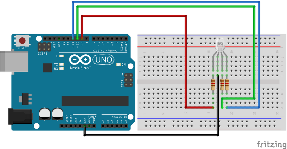
Step 1: Connect the RGB LED to the Breadboard
Start by placing the RGB LED on the breadboard, making sure to align the pins with the rows on the breadboard. The longer lead of the RGB LED is the common anode, which should be connected to the 5V pin on the Arduino. The shorter leads are the cathodes for each of the three individual LEDs.
Step 2: Connect the Resistors
Connect a 220 ohm resistor to each of the three cathode leads of the RGB LED. The other end of each resistor should be connected to a separate pin on the Arduino. Connect the red cathode to Pin 9, green to Pin 10, and blue to Pin 11.

Code
Step 3: Program the Arduino
Now that everything is connected, it's time to write the program. Open the Arduino IDE, create a new sketch, and copy the following code:
This program sets the LED to display red, green, and blue in sequence. You can customize the colors by adjusting the values passed to the digitalWrite() function. A value of HIGH turns the LED on, while a value of LOW turns it off.
Step 4: Upload the Program to the Arduino
Connect the Arduino to your computer and upload the program. Once the upload is complete, the RGB LED should light up and display the sequence of colors specified in the program.
Conclusion
In conclusion, connecting and programming an RGB LED with an Arduino is a simple and fun project that can be completed with just a few basic components. With the ability to customize the colors and patterns displayed by the LED, the possibilities are endless.