Voltage Dividers Explained
A voltage divider turns one voltage into a smaller one using two resistors in series. This post explains how the circuit works, derives the formula from first principles, works through two examples, and covers the loading effect, the one practical limit worth knowing before you wire one up.
1.0 Introduction
A voltage divider is one of the simplest circuits in electronics: two resistors in series, with the output voltage tapped from the junction between them. It shows up almost everywhere in Arduino work, reading a thermistor, scaling a 12 V signal down to fit an ADC, shifting a 5 V logic output to 3.3 V for a low-voltage device. The circuit itself takes seconds to understand. What takes a little longer is knowing when it works reliably and when it does not.
This post builds the formula from scratch using Ohm's Law, works through a couple of examples to make the calculation click, and then covers the loading effect, which is the part that catches most beginners off guard.
2.0 The Circuit
Two resistors, R1 and R2, are wired in series from the input voltage (V_in) to ground. The output voltage (V_out) is measured at the node between them.

Figure 1. Basic voltage divider circuit. R1 and R2 are in series; V_out is measured at the node between them.
R1 sits between V_in and the output node. R2 sits between the output node and ground. Because both resistors share the same series current, each one drops a fraction of V_in that is proportional to its share of the total resistance. R2's share, $\frac{R_2}{R_1 + R_2}$, is what appears at V_out.
3.0 The Voltage Divider Formula
3.1 Deriving the Formula
With R1 and R2 in series, the total resistance is $R_1 + R_2$. From Ohm's Law, the current through the series pair is:
$$I = \frac{V_{in}}{R_1 + R_2}$$
That same current flows through R2. The voltage across R2 is V_out, so:
$$V_{out} = I \times R_2$$
Substituting I:
$$V_{out} = \frac{V_{in}}{R_1 + R_2} \times R_2$$
Simplified:
$$V_{out} = V_{in} \times \frac{R_2}{R_1 + R_2}$$
That is the voltage divider formula. V_out is always a fraction of V_in (as long as R1 is not zero), and the ratio $\frac{R_2}{R_1 + R_2}$ controls exactly how large that fraction is. Change either resistor and the fraction changes.
3.2 Worked Examples
Example 1: Finding V_out from known resistors
V_in = 12 V, R1 = 10 kΩ, R2 = 5 kΩ. What is V_out?
$$V_{out} = 12 \times \frac{5}{10 + 5}$$
$$V_{out} = 12 \times \frac{1}{3} = 4 \text{ V}$$
Example 2: Choosing resistors for a target output
You need 3.3 V from a 5 V supply, which is a common requirement when connecting a 5 V Arduino output to a 3.3 V device. What resistor ratio do you need?
Rearrange the formula to find the ratio:
$$\frac{V_{out}}{V_{in}} = \frac{R_2}{R_1 + R_2} \quad \Rightarrow \quad \frac{3.3}{5} = 0.66$$
R2 needs to be 66% of the total resistance. A convenient standard-value pair that achieves this: R1 = 10 kΩ and R2 = 20 kΩ.
$$V_{out} = 5 \times \frac{20}{10 + 20}$$
$$V_{out} = 5 \times \frac{2}{3} = 3.33 \text{ V}$$
4.0 The Loading Effect
This is the part most tutorials skip, and the most common source of confusion when a divider behaves differently on the bench than it did in the calculation.
The formula above assumes nothing draws current from the V_out node. Connecting a load changes that. The load resistance R_L sits in parallel with R2, and any parallel combination is always smaller than either resistor alone. The effective lower resistance drops, which pulls V_out down.
The effective lower resistance once a load is connected:
$$R_{eff} = \frac{R_2 \times R_L}{R_2 + R_L}$$
And V_out becomes:
$$V_{out} = V_{in} \times \frac{R_{eff}}{R_1 + R_{eff}}$$

Figure 2. The loading effect. R_L in parallel with R2 reduces the effective lower resistance and pulls V_out below the ideal value.
The error grows as R_L gets smaller relative to R2. If R_L equals R2, the effective lower resistance is halved and V_out drops noticeably. If R_L is 10 times R2, the error is roughly 9%. If R_L is 100 times R2, it falls under 1%.
Practical rule: keep R_L at least 10 times larger than R2 if you need V_out to stay within about 10% of the ideal value [1], [2].
This is also why you cannot power a device from a voltage divider. A load that draws real current has a low effective resistance, and that collapses the output voltage. If you need a stable, load-tolerant voltage, use a proper voltage regulator instead.
5.0 Practical Uses
5.1 Reading a Resistive Sensor
The most common use of a voltage divider in Arduino work is pairing it with a resistive sensor such as an NTC thermistor or an LDR (light-dependent resistor). One arm of the divider is a fixed resistor; the other is the sensor, whose resistance changes with temperature or light. As the sensor resistance shifts, the junction voltage shifts with it, and the Arduino reads that changing voltage through an analog input pin.

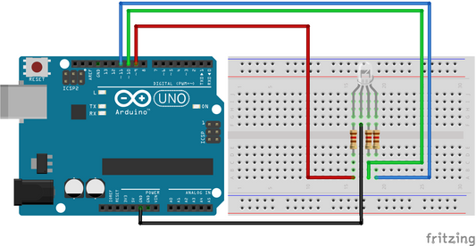
Figure 3. Resistive sensor voltage divider. R1 is a fixed 10 kΩ resistor; R2 is an NTC thermistor. The midpoint feeds Arduino A0.
For an NTC 10k thermistor paired with a 10 kΩ fixed resistor and a 5 V supply:
$$V_{out} \text{ at 25°C} = 5 \times \frac{10}{10 + 10} = 2.5 \text{ V}$$
As temperature rises, the NTC resistance drops, and V_out drops with it. That falling voltage is what the Arduino reads and converts to a temperature value.
One practical limit here: Arduino's 10-bit ADC works most accurately when the source impedance feeding it is 10 kΩ or below [3]. With a 10 kΩ fixed resistor and a 10 kΩ thermistor, the source impedance at the midpoint is roughly R1 in parallel with R2, which is 5 kΩ. That's within spec. If you use higher-value resistors to save power, keep an eye on this limit.
5.2 Scaling Voltage for an ADC
If a sensor produces a voltage higher than the ADC's reference (5 V on most Arduino boards), you need to scale it down before reading it. A voltage divider does this cleanly, provided the signal changes slowly enough that the RC time constant of the resistors and wiring is not a limiting factor.
Using the numbers from Example 1 above: a 12 V signal through R1 = 10 kΩ and R2 = 5 kΩ gives 4 V at the ADC input, comfortably within the 5 V range.
5.3 Logic Level Shifting
When a 5 V Arduino needs to send a signal to a 3.3 V device, a voltage divider on the output line is the simplest way to shift the level. R1 = 10 kΩ and R2 = 20 kΩ brings a 5 V HIGH down to 3.33 V.
This approach has real limits though. It only works in one direction (5 V to 3.3 V, not the reverse), and the RC time constant of the resistor network and any line capacitance limits how fast the signal can switch reliably. For slow signals like sensor reads or basic I2C at 100 kHz, it works. For faster buses or bidirectional lines, use a dedicated level-shifting IC instead.
6.0 Choosing Resistor Values
Once you know the ratio you need, there are two competing pressures on the actual component values:
- Lower values (1 kΩ to 10 kΩ range) reduce loading sensitivity and keep the output voltage stable even if the load impedance is on the lower side. The downside is higher quiescent current and more power wasted in the resistors.
- Higher values (100 kΩ and above) minimise quiescent current and power dissipation, but the output becomes more sensitive to loading and to parasitic capacitance on the output line, which limits signal speed.
For most Arduino ADC and sensor-reading applications, 10 kΩ is a sensible default. It keeps power consumption low enough to ignore, stays within the ADC source impedance limit, and keeps loading error negligible when feeding a high-impedance input. If power consumption is critical (battery-powered projects), go higher and add an op-amp voltage follower to buffer the output.
7.0 Project Ideas to Try Next
- Build a simple divider from two resistors and a multimeter. Set up R1 = 10 kΩ and R2 = 10 kΩ, connect 5 V, and measure V_out. Then touch the multimeter probe to the output while measuring a second time and watch whether the reading shifts slightly: that is the loading effect from the meter's own input impedance in action.
- Wire up a thermistor voltage divider (10 kΩ NTC + 10 kΩ fixed resistor + 5 V supply) and read the analog voltage on an Arduino. Print the raw ADC value, then warm the sensor with your finger and watch the reading fall.
- Try scaling the output of a 9 V battery down to a safe ADC input voltage using a voltage divider. Calculate the resistor ratio, build the circuit, verify V_out with a multimeter, then confirm the ADC reading on the Arduino matches.
- Set up the 5 V to 3.3 V level-shift circuit (R1 = 10 kΩ, R2 = 20 kΩ) and verify the output with a multimeter before connecting it to any 3.3 V device.
8.0 Covered in This Tutorial
This post covered:
- How a voltage divider circuit works and why V_out is always a fraction of V_in.
- The formula $V_{out} = V_{in} \times \frac{R_2}{R_1 + R_2}$, derived step by step from Ohm's Law.
- Two worked examples: calculating V_out from known resistors, and finding the resistor ratio for a target output.
- The loading effect, and why the ideal formula only holds when R_L is much larger than R2.
- Three practical applications: reading a resistive sensor, scaling voltage for an ADC, and shifting logic levels from 5 V to 3.3 V.
Related reading: Ohm's Law (V = IR), What Is a Resistor, How Voltage Works.
9.0 Conclusion
A voltage divider is two resistors in series with the output taken from the junction between them. The formula follows directly from Ohm's Law: $V_{out} = V_{in} \times \frac{R_2}{R_1 + R_2}$. It works reliably when the load impedance is much higher than R2, and breaks down when the load draws real current. Keep that boundary in mind, choose resistor values that match your source impedance requirements, and the voltage divider becomes one of the most useful building blocks you will reach for repeatedly.
10.0 References
[1] R. L. Boylestad, Introductory Circuit Analysis, 13th ed. Boston, MA, USA: Pearson, 2016.
[2] P. Horowitz and W. Hill, The Art of Electronics, 3rd ed. Cambridge, UK: Cambridge University Press, 2015.
[3] Atmel, "ATmega328P 8-bit AVR Microcontroller with 32K Bytes In-System Programmable Flash Datasheet," Rev. 8271JS, 2015. [Online]. Available: https://www.microchip.com/en-us/product/atmega328p
[4] "Voltage Divider," HyperPhysics, Georgia State Univ. Accessed: Jun. 28, 2026. [Online]. Available: http://hyperphysics.phy-astr.gsu.edu/hbase/electric/voldiv.html
[5] "Voltage Dividers," SparkFun Learn. Accessed: Jun. 28, 2026. [Online]. Available: https://learn.sparkfun.com/tutorials/voltage-dividers/all